
Ring, Pin, Plug, Disc Measurement - Calibration
Plain cylindrical gages include ring, plug and pin gages, plus discs. All tolerances are in accordance with the Gage Maker’s Tolerance chart (below). In general plug, disc and ring gages are typically used in go/no go applications to measure the state of a production piece, not its size. Pin gages are typically used to measure size, not state. Applicable standards are:
1. ANSI/ASME B89.1.5-1998 (R2009), Measurement of Plain External Diameters for Use as Master Discs or Cylindrical Plug Gages
2. ANSI/ASME B89.1.6- 2002 (R2012), Measurement of Qualified Plain Internal Diameters for Use as Master Rings and Ring Gages
The ANSI/ASME standards do not dictate a contact force requirement when measuring pins, plugs and discs. For contact-based measuring instruments, Pratt & Whitney recommends that the contact force is the lowest force possible for which repeatable readings are assured. Other items to take into consideration:
1. Use a soak plate
2. Keep gages and masters close together
3. Allow enough “soak time” for gages to acclimate (2-24 hours, depending on gage size)
4. Measure gages quickly
5. Sandwich readings (master, gage1, gage2 . . . , master)
6. Use gloves or tongs to handle gages
7. Shield instrument from any noticeable drafts and/or vents
8. Master using the same material as the measured gages
Typical measurements for rings, plugs and discs are taken at three heights on one axis and repeated again on a second axis perpendicular to the first for a total of six measurements. These measurements are taken at distances 1/16 inch (0.063 inch) from the bottom and the top surface plus one at midpoint. Axes are usually called 0-degree and 90-degree whereas positions are named position 1 (bottom), position 2 (mid-height) and position 3 (top). Rings smaller than 0.150-inch typically require only two readings per axis in the center height region. Occasionally different positional terminology is used but a good certificate of calibration should make clear—usually with a diagram—its meaning.
|
Gagemaker's Tolerance Chart (English, Total tolerance) |
|||||||
|
Size Range (Inches) |
Tolerance by Class (micro-inches) |
||||||
|
> |
< |
XXX |
XX |
X |
Y |
Z |
ZZ |
|
0.010 |
0.825 |
10 |
20 |
40 |
70 |
100 |
200 |
|
0.825 |
1.510 |
15 |
30 |
60 |
90 |
120 |
240 |
|
1.510 |
2.510 |
20 |
40 |
80 |
120 |
160 |
320 |
|
2.510 |
4.510 |
25 |
50 |
100 |
150 |
200 |
400 |
|
4.510 |
6.510 |
33 |
65 |
130 |
190 |
250 |
500 |
|
6.510 |
9.010 |
40 |
80 |
160 |
240 |
320 |
640 |
|
9.010 |
12.010 |
50 |
100 |
200 |
300 |
400 |
800 |
|
12.010 |
15.010 |
75 |
150 |
300 |
450 |
600 |
1,200 |
|
15.010 |
18.010 |
100 |
200 |
400 |
600 |
800 |
1,600 |
|
18.010 |
21.010 |
125 |
250 |
500 |
750 |
1,000 |
2,000 |
Pratt & Whitney offers a number of machines suitable for calibrating plugs, pins and discs:
1. Labmaster Universal (Model 175, 1000M, 1000A)
2. Laser Measuring Machine
3. Labmicrometer (Model 900, 1600)
4. Digital Measuring Machine
5. Universal Supermicrometer (Model 501, 504)
6. External Supermicrometer (Model B, C, PC)
 Free USB
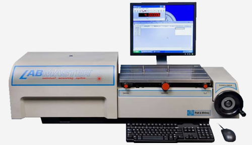 Product &
 Celebrating