
Thread Gage Measurement - Calibration
A thorough calibration of a parallel thread gage (internal or external) can be very time consuming, but with the proper instrument, it doesn't have to. Parameters requiring checks might include:
1. Pitch diameter
2. Major diameter (external) or minor diameter (internal)
3. Thread lead
4. Thread half-angle and
5. Thread drunkenness
General industrial practice is to confine thread calibration checks to pitch diameter and sometimes major/minor diameter. Although several methods exist to check pitch diameter, for external threads the three-wire method is most commonly used. For internal threads either use set plugs or the ball method, as appropriate. Major/minor diameter checks are done with plain ring/plug gages, as appropriate. Three-wire pitch diameter checks are commonly performed at the recommended force per ANSI/ASME B1.2 (English) or B1.16M (Metric). These ANSI/ASME standards also contain force suggestions for the ball method check of internal threads. These force recommendations are consolidated in the following chart:
|
ANSI/ASME Recommended Thread Calibration Force |
|||
|
External |
|||
|
English |
Metric |
||
|
TPI |
Force (oz) |
Pitch |
Force (oz/N) |
|
≤ 20 |
40 |
≥ 1.25 |
40 (11.1) |
|
> 20-40 |
16 |
0.6-1.25 |
16 (4.5) |
|
> 40-80 |
8 |
0.35-0.6 |
8 (2.2) |
|
> 80-140 |
4 |
0.2-0.35 |
4 (1.1) |
|
> 140 |
2 |
|
|
|
Internal |
|||
|
≤ 8 |
8 |
≥ 3 |
8 (2.2) |
|
8-20 |
6 |
1.25-3 |
6 (1.7) |
|
20-32 |
4 |
0.8-1.25 |
4 (1.1) |
External threads fall into one of three general categories:
1. Product threads.
2. X-tolerance gages: directly check product threads on the assembly line.
3. W-tolerance gages: thread-setting plug gages (a.k.a. “set plugs”). Used to check X-tolerance thread ring gages in a temperature-controlled calibration lab. These tolerances are smaller than X-tolerance.
To measure external thread pitch diameter use the best size wire whenever possible. Best size wires contact the gage at the pitch diameter thus avoiding any errors caused by thread angle deviation. Internal thread pitch diameter is checked as follows:
1. X-tolerance (split, adjustable thread rings): Use set plugs (W tolerance).
2. W-tolerance (solid rings): Either use set plugs (W tolerance) or the ball method. If the later, it’s recommended that the ball size match the best wire size for that TPI (Pitch).
Common formulas (simplified 1) used to calculate pitch diameter are:
1. 60º external: E = M + P * Cos 30 – 3 * W
2. 60º internal: E = M – P * Cos 30 + B
3. 55º external: E = M + 0.9605 * P – 3.1657 * W
4. 29º external: E = M + 1.933357 * P – 4.9939 * W
Wire sizes may be calculated as follows:
1. 60º:
a. Best: W (best) = 0.57735 * P
b. Minimum: W (min) = 0.505182 * P
c. Maximum: W (max) = 1.010363 * P
2. 55º (Whitworth) best: W (best) = 0.56368 * P
3. 29º (ACME) best: W (best) = 0.51645 * P
Where:
E = Pitch diameter
M = Measurement over wires, i.e., the machine readout
TPI = Threads-Per-Inch
P = Pitch of the gage (1/TPI)
W = Calibrated thread wire size
B = Calibrated ball size
1 The full formula for pitch diameter corrects the small error (trending undersize) caused by “lead angle”. This error occurs because the wire is not perpendicular to the thread axis. Lead angle is inversely proportional to TPI.
 Free USB
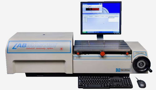 Product &
 Celebrating