
Geometric Analysis of Adjustable Thread Ring Gages
Abstract
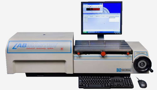
This paper summarizes a first-order geometric analysis of measurement error in adjustable thread ring gages caused by measuring away from the thread contact locations. The analysis models the ring as three rigid circular segments connected by two compliant joints. Each segment retains constant pitch-cylinder curvature while the ring is adjusted to fit a master setting plug. A practical measurement approach is also discussed for laboratories wishing to characterize a standard three-segment AGD adjustable thread ring on a Labmaster Universal (LMU) when a setting plug is unavailable.
1. Problem Statement
Each segment is modeled as a rigid circular arc having pitch-cylinder curvature diameter D2. The assembled ring is adjusted to fit a master plug of pitch diameter D1. Contact occurs at three locations spaced 120° apart. Diameter measurements are taken at two diametrically opposite points located 30° from the compliant joints rather than at the contact locations.
2. Assumptions
- Two-dimensional geometry.
- Segment curvature remains constant during adjustment.
- Segments are tangent to the master plug at the three contact points.
- Elastic deformation of the segments, threads, and joints is neglected.
- Measurement is made on the pitch cylinder.
3. Exact Result
Let R1=D1/2 and R2=D2/2. If α is the angular offset between the contact point and the measurement point, the measured diameter is:
Dmeas = -(D2-D1) cos(α) + sqrt(D2^2 - (D2-D1)^2 sin^2(α)).
For the present geometry α = 30°. The measurement error is E = Dmeas - D1.
4. Small-Mismatch Approximation
For |D2-D1| << D1,
E ≈ (1-√3/2)(D2-D1) - (D2-D1)^2/(8D1).
To first order,
E ≈ 0.133975 (D2-D1).
Thus approximately 13.4% of the difference between the segment curvature diameter and the fitted pitch diameter appears as measurement error due solely to measuring away from the contact locations.
5. Discussion
D2 represents the pitch-cylinder curvature diameter of each rigid segment before assembly, not the ring adjustment range. Consequently, D2-D1 is expected to be much smaller than the total adjustment capability of the ring. Based on engineering judgment, a new adjustable ring may have D2-D1 on the order of a few ten-thousandths of an inch, although this value is manufacturer-dependent and has not been confirmed from design drawings.
6. Estimated Error Magnitude
If D2-D1 = 0.0002 in, the first-order model predicts approximately 27 µin error.
If D2-D1 = 0.0005 in, approximately 67 µin.
If D2-D1 = 0.0010 in, approximately 134 µin.
The (3) error values above are within 0.1% of values determined from a CAD layout.
7. Limitations
The model intentionally ignores elastic deformation, distributed thread contact, local flank geometry, lead error, and compliance of the joints. Actual commercial adjustable thread rings may exhibit smaller or differently distributed errors because contact occurs over multiple thread flanks and the segments undergo small rotations and elastic deformation during setting. For the standard three-segment AGD ring considered here, the principal LMU limitation is the geometric offset between the setting-plug contact locations and the opposed LMU measurement locations. Repeating the same two-point measurement at many circumferential angles does not remove that geometry error and is not necessary for the LMU characterization discussed in this paper.
8. Standards-Based Calibration vs. LMU Characterization
For adjustable (split) thread ring gages, the preferred and standards-based practice remains setting the ring to the applicable calibrated thread setting plug. PWMS thread-calibration guidance likewise identifies X-tolerance adjustable thread rings as being checked with W-tolerance setting plugs. A setting plug evaluates the ring by distributed threaded engagement and is therefore a functional reference rather than a single local diameter measurement.
An LMU can still provide valuable dimensional information when a setting plug is unavailable. For the standard three-segment AGD ring analyzed in this paper, a practical LMU characterization is obtained by measuring at three axial heights while holding the circumferential orientation fixed. The three values are used primarily to identify axial taper or localized wear. The calculated geometric offset associated with measuring away from the setting-plug contact points should be included explicitly in the measurement uncertainty analysis.
9. Scope of the LMU Characterization
The three-height measurement approach is intentionally limited. Its purpose is to obtain useful pitch-diameter information and to reveal axial taper or localized wear without adding a large number of measurements that do not address the dominant geometric limitation. For the standard three-segment AGD geometry analyzed here, the primary concern is the predictable difference between the setting-plug contact geometry and the LMU measurement geometry.
A more elaborate circumferential mapping program is not required for this purpose. If a separate investigation of roundness is desired, that should be treated as a different metrology problem and evaluated with a measurement method suited to form analysis. Such additional form measurements do not replace the functional setting-plug check.
10. Southern Style / True Round Adjustable Thread Rings
The geometric analysis presented in this paper applies specifically to the conventional three-segment AGD-style adjustable thread ring. Southern Style (True Round) adjustable rings use a different adjustment mechanism designed to maintain roundness as the ring is adjusted. Consequently, the contact-location error derived for the three-segment AGD geometry should not be applied to Southern Style rings.
Because a Southern Style ring is designed to remain substantially round during adjustment, direct pitch-diameter measurement on an LMU may be more representative of the functional diameter than it is for a conventional three-segment AGD ring. The ring can therefore be measured at the top, middle, and bottom axial positions to evaluate pitch diameter and taper. The relationship between the LMU measurement and the functional setting-plug condition should be established experimentally before the LMU method is treated as equivalent to, or used in place of, the setting-plug method. A calibrated setting plug remains the preferred functional reference.
11. Conclusions
- A closed-form geometric solution was derived.
- The first-order sensitivity is approximately 0.134(D2-D1).
- The predicted error depends primarily on the difference between the segment pitch-cylinder curvature diameter and the fitted setting-plug pitch diameter.
- The geometric model predicts that measurement errors will decrease if the ring gage gets uniformly worn.
- For adjustable thread ring gages, the calibrated setting plug remains the preferred functional reference; an LMU measurement should be treated as dimensional characterization unless a validated alternative procedure has been established.
- For the standard three-segment AGD ring considered here, measurements at three axial heights at a fixed circumferential orientation provide a practical means of evaluating axial taper or localized wear.
- The three readings are used primarily to evaluate axial taper or localized wear. The calculated contact-location geometry error should be included in the measurement uncertainty analysis because additional circumferential readings do not remove that inherent geometric offset.
12. References and Technical Basis
1. ASME B1.2-1983 (R2017), Gages and Gaging for Unified Inch Screw Threads.
2. Pratt & Whitney Measurement Systems, “Thread Gage Measurement - Calibration,” guidance for internal pitch-diameter measurement and use of setting plugs for X-tolerance adjustable thread rings.
 Free USB
 Product &
 Celebrating